


Langue
FR
Saisissez des mots-clés...


NOUVEAU

Comment identifier les raccords hydrauliques ?
 2026.07.13
 nouvelles de l'industrie
La réponse directe
Vous identifiez un raccord hydraulique en vérifiant quatre éléments dans l'ordre : le modèle de filetage sur la connexion, le siège et l'angle où il scelle, le diamètre extérieur et le pas de filetage mesurés avec un pied à coulisse ou une jauge de filetage, et la forme du corps du raccord tel que droit, coudé, en T ou un adaptateur. La plupart des confusions sur le terrain proviennent du mélange de modèles de filetage qui semblent presque identiques, donc mesurer est toujours plus fiable que deviner à l'œil nu.
Une fois que vous connaissez la famille de filetage, qu'il s'agisse de TNP, JIC 37 degrés, ORFS, BSPP, BSPT, métrique ou AN flare, vous pouvez la comparer à un tableau des tailles et confirmer avec une jauge de filetage. Le reste de ce guide passe en revue chaque étape de ce processus, ainsi que les sujets connexes relatifs aux raccords de flexibles hydrauliques, aux raccords hydrauliques AN, aux raccords de pompe hydraulique, aux types de flexibles hydrauliques, aux raccords d'extrémité de flexibles, aux types de connecteurs de flexibles hydrauliques et à la durée réelle d'utilisation des flexibles hydrauliques.
NPT JIC 37 degrés ORFS BSPP BSPT DIN métrique UNE fusée éclairante Bride SAE
Qu'est-ce qu'un tuyau hydraulique
Avant d’identifier un raccord, il est utile de comprendre à quoi il est attaché. Un tuyau hydraulique est un tube flexible conçu pour transporter un fluide sous pression entre les pompes, les vannes, les cylindres et les moteurs d'un système hydraulique. Contrairement à un simple tuyau d'arrosage en caoutchouc, un tuyau hydraulique est construit en couches : une chambre à air qui résiste au fluide hydraulique spécifique, une ou plusieurs couches de renfort en fil d'acier tressé ou en spirale qui donnent au tuyau sa pression nominale, et une gaine extérieure qui protège contre l'abrasion, les intempéries et l'exposition aux produits chimiques.
Le raccord est le connecteur métallique serti, serti ou vissé à l'extrémité de ce tuyau afin qu'il puisse être relié à une pompe, un cylindre, un bloc de vannes ou un autre tuyau. Étant donné que le tuyau lui-même est flexible et que le raccord est rigide, le raccord est le point de départ de presque toutes les fuites, éruptions et pannes, c'est exactement pourquoi une identification correcte est si importante avant de commander une pièce de rechange.
Un tuyau hydraulique industriel typique est évalué à 2 000 psi pour les conduites de retour légères jusqu'à 6 000 psi ou plus pour les travaux à haute pression tels que les vérins de flèche d'excavatrice. Le raccord fixé à ce tuyau doit correspondre à la fois à la pression nominale et au style exact de filetage ou de joint du port auquel il se connecte, sinon la connexion fuira même si le tuyau lui-même est en parfait état.
Les tuyaux sont également construits autour d'un composé de chambre à air spécifique choisi pour le fluide circulant dans le système. Le caoutchouc nitrile est le matériau de chambre à air le plus courant pour les fluides hydrauliques standard à base de pétrole, tandis que d'autres composés sont utilisés pour les fluides résistants au feu, les fluides à base d'ester de phosphate ou les applications de qualité alimentaire. L'utilisation d'un tuyau conçu pour le mauvais type de fluide peut faire gonfler, ramollir ou fissurer la chambre à air bien avant que la couche de renforcement ne s'use, ce qui constitue un mode de défaillance distinct de tout ce qui concerne le raccord lui-même.
Le rayon de courbure d'un tuyau est un autre facteur étroitement lié à l'identification et à l'installation correcte. Chaque tuyau a un rayon de courbure minimum spécifié par le fabricant, et son acheminement plus serré que ce rayon sollicite le renfort métallique au point de courbure à chaque fois que le système est mis sous pression. Au fil du temps, cette flexion répétée fatigue le fil bien avant que le reste du tuyau ne s'use normalement, et cela se manifeste très souvent d'abord par une défaillance directement au niveau du raccord, car c'est généralement le point le plus rigide et le moins indulgent de l'assemblage.
Nonte de terrain Un tuyau évalué à 4 000 psi avec un raccord dépareillé ou usé échouera toujours bien en dessous de sa pression nominale. Le maillon le plus faible d’une conduite hydraulique est presque toujours le point de raccordement, et non le tube flexible lui-même.
Que sont les raccords de tuyaux hydrauliques
Raccords de flexibles hydrauliques sont les raccords d'extrémité métalliques, les adaptateurs et les coupleurs qui relient un tuyau hydraulique à une pompe, un cylindre, une vanne, un filtre ou un autre tuyau. Ils effectuent trois tâches à la fois : ils fixent physiquement le tuyau au reste du système, ils créent un joint étanche à la pression afin que le fluide ne puisse pas s'échapper et, dans de nombreux cas, ils permettent à un technicien d'acheminer le fluide selon un angle ou un pas entre différentes tailles.
Chaque raccord de tuyau hydraulique est en réalité composé de deux moitiés qui doivent correspondre : l'extrémité de sertissage ou de fixation qui saisit le tuyau lui-même et l'extrémité de connexion qui s'accouple avec l'orifice, la vanne ou le raccord opposé. Une mauvaise extrémité à sertir signifie que le tuyau peut exploser sous pression. Une mauvaise extrémité de connexion signifie que le joint fuira, se croisera ou ne s'emboîtera tout simplement jamais.
Les trois parties dont dépend chaque identification de raccord
- Type de fil : le motif découpé dans le métal, tel que NPT, JIC, BSPP ou métrique, qui détermine la manière dont le raccord se visse.
- Style de siège : la forme interne qui crée réellement le joint, comme un évasement à 37 degrés, une face de joint torique ou un filetage de tuyau conique qui assure l'étanchéité sur les filetages eux-mêmes.
- Taille : le code de taille nominale, souvent écrit sous la forme d'un tiret tel que le tiret 6 ou le tiret 8, faisant référence au diamètre intérieur du tuyau en seizièmes de pouce.
Il est utile de se rappeler que le type de fil de discussion et le style de siège sont des variables indépendantes, même s’ils sont souvent regroupés dans une conversation informelle. Deux raccords peuvent partager exactement le même modèle de filetage et le même diamètre extérieur tout en scellant de manière complètement différente, c'est exactement pourquoi la mesure du filetage seul ne suffit pas toujours pour terminer une identification. Un raccord à filetage droit, par exemple, peut sceller avec une rondelle collée, un joint torique sur une face ou un joint torique dans une rainure sur la tige, et chacun d'eux nécessite une pièce d'accouplement différente même si les filetages eux-mêmes se vissent très bien.
C’est également là que de nombreuses pièces de rechange contrefaites ou dépareillées posent problème. Un raccord qui semble correct et qui se visse en douceur peut toujours être du mauvais style de siège, ce qui empêche la formation d'un joint approprié ou, dans le pire des cas, permet à la connexion d'être suffisamment serrée pour paraître sécurisée tout en fuyant progressivement sous pression.
Types de raccords hydrauliques expliqués
Lorsque les gens posent des questions sur les types de raccords hydrauliques, ils se posent généralement deux questions différentes à la fois : quelle est la forme du raccord et quel filetage ou quelle norme d'étanchéité utilise-t-il. Les deux sont importants, et une identification correcte nécessite les deux réponses.
Par forme et fonction
| Forme d'ajustement | Ce qu'il fait | Cas d'utilisation courant |
|---|---|---|
| Adaptateur droit | Connecte deux ports ou extrémités de tuyaux en ligne directe | Raccordement pompe-tuyau |
| coude à 90 degrés | Change de direction à angle droit pour économiser de l'espace | Orifices de cylindre serrés sur les pelles |
| coude à 45 degrés | Change progressivement de direction avec moins de restriction de débit | Acheminement du groupe de vannes |
| Raccord en T | Les divisions ou les jointures se déroulent dans une troisième ligne | Alimentation de deux circuits à partir d'une seule ligne de pompe |
| Montage en croix | Divise le flux en trois directions supplémentaires | Blocs collecteurs avec plusieurs jauges |
| Réducteur ou expanseur | Étapes entre deux tailles de tuyaux différentes | Connexion d'un tuyau Tiret 8 à un port Tiret 6 |
| Adaptateur pivotant | Permet la rotation sans tordre le tuyau | Tuyaux qui fléchissent lors du mouvement de l'équipement |
| Bouchon et bouchon | Scelle complètement un port inutilisé | Blocage d'une sortie de pompe de rechange |
Par norme de filetage et de joint
C’est la catégorie qui suscite le plus de confusion, car plusieurs normes de filetage semblent presque identiques à un œil non averti. Le tableau ci-dessous est le moyen le plus rapide de préciser ce que vous détenez.
| Norme | Méthode de scellement | Angle de filetage | Indice visuel |
|---|---|---|---|
| NPT (tuyau national conique) | Joints sur filetages coniques, souvent avec du mastic | 60 degrés, conique | Fils visiblement étroits vers la pointe |
| NPSM (droit) | Joints par rondelle ou joint torique, filetage droit | 60 degrés, droit | Les fils restent de la même largeur le long de la tige |
| JIC 37 degrés | Scelle sur un cône évasé de 37 degrés | Flare à 37 degrés | Siège en forme de cône visible à l'intérieur du raccord |
| Évasement SAE à 45 degrés | Scelle sur un cône évasé à 45 degrés | Évasement à 45 degrés | Angle d'évasement plus faible que celui du JIC |
| ORFS (joint torique) | Joints avec un joint torique sur face plane | Filetage droit, face plate | Rainure de joint torique en caoutchouc visible sur une face plate |
| BSPP (parallèle britannique) | Joints avec rondelle collée, filetage droit | 55 degrés, droit | Crête de fil arrondie, souvent estampillée d'un G |
| BSPT (conique britannique) | Joints sur filetages coniques | 55 degrés, conique | Similaire au NPT mais profil de filetage plus rond |
| DIN métrique | Joints avec un joint torique captif ou un anneau de morsure | 60 degrés, droit or tapered variants | Taille indiquée en millimètres et non en pouces |
Erreur courante Les filetages NPT et BSPT semblent presque identiques et commencent souvent à s'enfiler ensemble, puis à se lier ou à fuir une fois serrés. Confirmez toujours avec une jauge de pas de filetage avant de supposer une correspondance, en particulier sur les équipements importés où BSPP et BSPT sont courants.
AN Raccords hydrauliques expliqués
Les raccords hydrauliques AN, parfois recherchés comme raccords hydrauliques, tirent leur nom de la spécification Army Navy initialement développée pour les conduites de carburant et hydrauliques des avions. Depuis, ils sont devenus courants dans les applications automobiles de performance, de sport automobile et dans certaines applications hydrauliques mobiles en raison de leur solide joint évasé à 37 degrés et de leur conception réutilisable fiable.
Un raccord AN assure l'étanchéité à l'aide d'un évasement de 37 degrés, ce qui correspond mécaniquement au même angle d'assise qu'un raccord JIC. En fait, les raccords AN et JIC de même taille de tableau de bord sont généralement interchangeables, ce qui explique pourquoi les gens confondent souvent les deux noms. La vraie différence réside principalement dans la convention d'étiquetage et la classe de filetage plutôt que dans la géométrie du joint elle-même.
Comment fonctionne un dimensionnement
Les raccords AN sont dimensionnés à l'aide d'un système de numéros en tirets, où le numéro fait référence au diamètre extérieur du tube en seizièmes de pouce. Un raccord Dash 6 AN mesure six seizièmes de pouce, soit trois huitièmes de pouce. Un tiret 8 équivaut à huit seizièmes, ou un demi-pouce. Il s'agit de la même logique de numérotation utilisée pour les raccords JIC, ce qui constitue une autre raison pour laquelle les deux familles sont si souvent confondues sur le terrain.
| Taille du tiret | Diamètre extérieur du tube | Utilisation typique |
|---|---|---|
| Tiret 4 | Quart de pouce | Conduites de jauge, petites conduites de carburant |
| Dash 6 | Trois huitièmes de pouce | Alimentation carburant, petits circuits hydrauliques |
| Dash 8 | Demi-pouce | Direction assistée, conduites hydrauliques moyenne pression |
| Tiret 10 | Cinq huitièmes de pouce | Circuits hydrauliques plus grands, refroidisseurs d'huile |
| Tiret 12 | Trois quarts de pouce | Conduites hydrauliques et de transmission à haut débit |
Conseil d'identification Recherchez d'abord l'angle d'évasement. Un véritable raccord AN ou JIC possède un siège visible en forme de cône à 37 degrés à l'intérieur du raccord. Si le siège est plat avec une rainure de joint torique, vous envisagez un raccord ORFS, pas un raccord AN, même si la taille du filetage semble similaire.
Matériaux de montage et placage comme indices d'identification
Le métal à partir duquel un raccord est fabriqué et le placage sur sa surface peuvent affiner son identité avant même que vous ne preniez un étrier. La plupart des raccords hydrauliques sont usinés en acier au carbone, en acier inoxydable ou en laiton, et chaque matériau a tendance à apparaître à des endroits prévisibles au sein d'un système.
| Matériel | Apparence typique | Où vous le trouverez |
|---|---|---|
| Acier au carbone zingué | Fini argent brillant à légèrement jaune | Norme mobile hydraulic hose fittings and adapters |
| Acier chromé | Finition hautement réfléchissante, semblable à un miroir | Conduites hydrauliques axées sur l'automobile et l'apparence |
| Acier inoxydable | Gris mat terne, résiste à la corrosion, non magnétique dans certains grades | Systèmes de fluides de qualité alimentaire, marins ou corrosifs |
| Laiton | Ton or jaune, métal plus doux | Conduites d'air basse pression et hydrauliques légères, jauges |
| Acier oxydé noir | Finition noir mat | Certains ports de pompe et blocs de vannes industriels |
Le placage et le métal de base ne vous indiqueront pas à eux seuls la norme de filetage, mais ils limitent rapidement l'application probable. Un raccord en laiton sur une conduite de cylindre haute pression, par exemple, est inhabituel et mérite une double vérification, car le laiton est généralement réservé aux circuits à basse pression. Un raccord en acier inoxydable apparaissant dans un système autrement entièrement en acier signale souvent la présence d'un fluide corrosif ou d'une pièce de rechange de qualité marine, ce qui constitue un indice utile pour remonter à la famille de filetage et à la pression nominale correctes.
Vérification rapide Placez un petit aimant près du raccord. L'acier au carbone et la plupart des nuances d'acier inoxydable utilisées dans les raccords structurels réagiront différemment à un aimant que l'acier inoxydable austénitique, vous donnant ainsi un tri rapide avant le début de toute mesure.
Outils dont vous avez besoin pour identifier les raccords hydrauliques
Une identification correcte dépend bien plus de la possession des bons outils que de la mémorisation de chaque norme. Un petit kit conservé dans un tiroir de magasin ou dans un camion de service résoudra la grande majorité des questions d'identification en moins d'une minute.
Pied à coulisse numérique
Mesure le diamètre extérieur des filetages mâles et le diamètre intérieur des ports femelles avec précision au centième de millimètre ou au millième de pouce, ce qui est essentiel pour séparer les tailles de filetage proches.
Jauge de pas de filetage
Un ensemble pliant de lames fines découpées avec différents motifs de filetage. Faire correspondre une lame contre le raccord confirme le pas de filetage par pouce ou millimètre en quelques secondes.
Jauge d'angle de siège
Un simple outil de style rapporteur ou un modèle imprimé utilisé pour confirmer si un siège évasé est coupé à 37 degrés ou à 45 degrés, puisque les deux se regardent de très près à l'œil nu.
Tableau d'identification des raccords
Un tableau imprimé ou plastifié faisant référence au diamètre extérieur et au nombre de fils par rapport à chaque norme commune, idéalement conservé à côté de l'étrier pour référence immédiate.
Brosse métallique et nettoyant
Élimine la crasse, le vieux mastic et la corrosion afin que les filetages et les numéros de pièces estampés soient réellement lisibles avant de mesurer quoi que ce soit.
Raccords d'échantillon de référence
Un petit ensemble étiqueté de bons raccords connus dans l'atelier, utilisé pour comparer côte à côte une pièce inconnue à une norme connue et confirmée.
Raccords de pompe hydraulique
Les raccords de pompe hydraulique sont des connecteurs montés directement sur les ports d'entrée et de sortie de la pompe, ainsi que sur l'orifice de vidange du boîtier sur de nombreuses pompes à engrenages et à piston. Ce sont quelques-uns des points de connexion les plus soumis aux contraintes de tout le système, car la pompe génère la pression à laquelle tout ce qui se trouve en aval doit résister.
Les fabricants de pompes spécifient généralement l'une des rares normes de filetage d'orifice, le plus souvent des orifices à filetage droit SAE avec joint torique, des orifices coniques NPT ou des orifices métriques sur les pompes construites en Europe. Identifier correctement l'orifice avant de commander un raccord évite une erreur très courante et coûteuse : forcer un raccord NPT conique dans un orifice de joint torique SAE droit, ce qui pourrait fissurer le boîtier de la pompe.
Les différences de pression nominale entre les ports d’une même pompe méritent également d’être comprises à des fins d’identification. Une pompe à engrenages conçue pour une pression de service d'environ 3 000 psi à la sortie peut avoir un orifice d'entrée évalué à seulement quelques psi de résistance au vide et un drain de boîtier bien en dessous. L'installation d'un connecteur haute pression sur le drain du boîtier n'est pas une erreur, mais l'installation d'un raccord sous-dimensionné ou de faible qualité sur l'orifice de sortie est l'une des causes les plus courantes de défaillance précoce des raccords de pompe sur le terrain, car cette connexion voit la pleine pression du système et les pics de pression dus au choc du cylindre ou de la vanne.
De nombreux fabricants d'équipements mobiles standardisent les ports à bossage de joint torique à filetage droit SAE sur l'ensemble de leur gamme de produits, en particulier parce qu'ils assurent une étanchéité fiable à une large plage de pressions sans recourir à un produit d'étanchéité pour filetage. Lors du remplacement d'un raccord sur ce type de port, le joint torique lui-même est généralement la première chose à inspecter, car un joint torique durci, aplati ou manquant est une cause beaucoup plus fréquente de fuite d'un raccord de pompe qu'un filetage véritablement mal assorti.
Comment identifier un port de pompe
- Recherchez une rainure de joint torique visible usinée dans la face du port ou l'épaulement. S'il est présent, il s'agit presque toujours d'un port à filetage droit SAE et non NPT.
- Mesurez le filetage avec un pied à coulisse sur tout le diamètre extérieur, puis vérifiez le nombre de fils par pouce avec une jauge de pas de filetage.
- Vérifiez si les filetages se rétrécissent vers l'ouverture. Un cône visible suggère fortement NPT ou BSPT plutôt qu'un port fileté droit.
- Faites référence au tableau des ports du fabricant de la pompe en utilisant le numéro de modèle de la pompe, car la plupart des fabricants publient les spécifications exactes des ports pour chaque modèle.
1
Port d'entrée
Généralement le plus grand port de la pompe, alimentant le fluide depuis le réservoir à basse pression. Souvent de taille plus grande que la sortie pour réduire le risque de cavitation.
2
Port de sortie
Transporte le fluide sous pression en aval vers les vannes et les actionneurs. Ce port et son raccord voient la pression de service la plus élevée dans la pompe.
3
Port de vidange du boîtier
Un port plus petit et basse pression qui renvoie les fuites internes vers le réservoir. Confondre cela avec un port de pression est une erreur fréquente et coûteuse.
Aperçu des types de flexibles hydrauliques
Connaître les types de flexibles hydrauliques est important pour l'identification, car la construction du flexible affecte les raccords qui peuvent être sertis ou fixés en toute sécurité. Les tuyaux sont généralement classés en fonction de leur couche de renfort et de leur pression nominale, selon des normes telles que SAE 100R.
| Type de tuyau | Renfort | Plage de pression typique | Application commune |
|---|---|---|---|
| SAE100R1 | Fil d'acier tressé simple | Jusqu'à 3 000 psi | Conduites de retour, circuits basse pression |
| SAE100R2 | Fil d'acier doublement tressé | Jusqu'à 5 000 psi | Hydraulique mobile générale |
| SAE100R12 | Quatre couches de fil en spirale | Jusqu'à 4 000 psi avec un alésage plus grand | Circuits hydrauliques à haut débit |
| SAE100R13 | Quatre à six couches de fil en spirale | Jusqu'à 6 000 psi | Matériel lourd de construction et d'exploitation minière |
| Tuyau thermoplastique | Tresse en fibres synthétiques | Jusqu'à 3 000 psi | Applications légères et résistantes aux produits chimiques |
| Tuyau doublé PTFE | Acier inoxydable braid over PTFE core | Varie selon la construction | Fluides à haute température ou agressifs |
Le raccord fixé à un tuyau doit correspondre non seulement au filetage du port à l'autre extrémité, mais également à la construction du tuyau lui-même, car un raccord plus léger serti sur un tuyau en spirale lourd peut glisser sous la pression même s'il se visse parfaitement à l'autre extrémité.
Raccords d'extrémité de tuyau
Les raccords d'extrémité de tuyau sont des connecteurs spécifiques fixés en permanence au tuyau, par opposition aux adaptateurs lâches qui se vissent simplement entre deux raccords. Il existe trois méthodes de fixation principales utilisées pour relier un raccord d'extrémité de tuyau au tuyau lui-même.
Méthodes de pièce jointe
| Méthode | Comment ça marche | Réutilisable | Cadre typique |
|---|---|---|---|
| Serti (permanent) | Une machine à sertir comprime un manchon métallique autour du tuyau et du raccord | No | Production en usine et en atelier, méthode la plus courante |
| Champ attachable | Montage de vis ou de colliers sur le tuyau sans machinerie spéciale | Parfois | Réparations d'urgence, chantiers éloignés |
| Réutilisable screw type | Les composants du raccord se vissent ensemble autour de l'extrémité du tuyau. | Oui | Équipements plus anciens, ateliers de réparation à faible volume |
Lors de l'identification d'un raccord d'extrémité de tuyau sur un assemblage existant, vérifiez la virole, qui est le manchon métallique extérieur. Le modèle de virole, qu'il s'agisse d'une construction biseautée ou non, ainsi que de tout estampage du fabricant, pointe généralement directement vers le numéro de pièce de rechange correct sans avoir besoin de mesurer à partir de zéro.
Pourquoi c'est important La plupart des fabricants de tuyaux et de raccords apposent un numéro de pièce ou un code de taille directement sur la virole ou sur l'hexagone du raccord. Avant de mesurer quoi que ce soit, vérifiez les marquages estampés, car cela seul confirme souvent l'identification exacte en quelques secondes.
Types de connecteurs de tuyaux hydrauliques comparés
Les types de connecteurs de tuyaux hydrauliques décrivent comment deux conduites ou composants distincts se rejoignent, ce qui est une question légèrement différente de la norme de filetage seule. Vous trouverez ci-dessous une comparaison pratique des styles de connecteurs que vous rencontrerez le plus souvent.
| Type de connecteur | Emplacement du joint | Points forts | À surveiller |
|---|---|---|---|
| Connecteurs Flare (JIC ou AN) | Joint conique métal sur métal | Solide, largement disponible, réutilisable | Peut être endommagé par un serrage excessif ou un évasement répété |
| Joint facial à joint torique (ORFS) | Joint torique comprimé contre une face plate | Excellente résistance aux fuites, résistant aux hautes pressions | Le joint torique doit être remplacé s'il est réutilisé, ne jamais réutiliser un joint endommagé |
| Connecteurs filetés NPT | Interférence de filetage conique | Simple, pas cher, largement approvisionné | Sujet aux fuites en cas de serrage excessif ou insuffisant |
| Connecteurs à bride (code SAE 61 et code 62) | Joint torique ou joint entre deux brides plates fixé par des boulons | Gère bien les très hautes pressions et les grands alésages | Nécessite un modèle de couple de boulon correct pour sceller correctement |
| Coupleurs à déconnexion rapide | Vanne à clapet interne avec joints toriques | Connexion et déconnexion rapides sans outils | Chute de pression plus élevée qu'un connecteur fixe |
| Connecteurs à came et à rainure | Joint comprimé par un mécanisme à levier de verrouillage | Très rapide à connecter, courant sur les flexibles de transfert | Pression nominale généralement inférieure à celle des autres types |
Raccords métriques ou impériaux : identification rapide
Les équipements fabriqués en Amérique du Nord utilisent généralement des filetages impériaux tels que les ports filetés droits NPT, JIC et SAE, tandis que les équipements construits en Europe et dans une grande partie de l'Asie utilisent fréquemment des filetages métriques conformes aux spécifications DIN ou OIN. Des flottes mixtes, des machines importées et des pièces de rechange signifient que les deux peuvent apparaître sur le même chantier, donc un moyen rapide de trier les uns des autres évite beaucoup de gaspillage de mesures.
| Indice | Suggère Impérial | Suggère une métrique |
|---|---|---|
| Origine du fabricant | Marque ou équipement nord-américain | Marque ou équipement européen ou asiatique |
| Diamètre mesuré | Chute de près d'une fraction de pouce, par exemple trois huitièmes ou un demi-pouce | Se rapproche d'un chiffre millimétrique rond tel que 14 ou 18 millimètres |
| Marquage estampé | Taille estampillée sous forme de tiret ou de fraction | Taille estampillée directement en millimètres, souvent avec un préfixe M |
| Forme de la crête du fil | Profil plus net à 60 degrés commun sur NPT et JIC | Souvent une crête arrondie sur DIN et certaines variantes ISO |
Lorsqu'une lecture au pied à coulisse se situe entre deux fractions impériales standard mais s'aligne étroitement avec un chiffre métrique rond, cette inadéquation est généralement le signe le plus clair que vous tenez réellement un raccord métrique plutôt qu'un raccord impérial usé ou de taille étrange. Convertir la lecture en millimètres avant de comparer avec un graphique évite beaucoup de temps perdu à essayer de forcer une correspondance impériale qui n'a jamais existé.
Exemples d'identification du monde réel
Travailler sur quelques scénarios concrets rend la liste de contrôle plus facile à appliquer dans des conditions réelles.
Exemple 1 : ligne de cylindre de flèche d'excavatrice
Un technicien retire un raccord qui fuit d’un vérin de flèche d’excavatrice. Le siège a une forme de cône visible, le diamètre extérieur mesure près d'un pouce et un seizième et une jauge de pas de filetage confirme 12 filetages par pouce. Un référencement croisé à un tableau des tailles JIC identifie ceci comme un raccord Dash 12 JIC à 37 degrés, cohérent avec les exigences de débit et de pression élevées d'un circuit de vérin de flèche.
Exemple 2 : port d'entrée de pompe importé
Une pompe de remplacement provenant d'un fournisseur européen possède un port qui n'acceptera pas un raccord NPT standard, se liant après seulement un tour ou deux. La mesure du diamètre extérieur donne une lecture proche de 33 millimètres plutôt qu'une fraction impériale propre, et les filetages ont une crête sensiblement plus ronde. Cela indique un port DIN métrique plutôt que NPT, et la commande d'un adaptateur métrique résout le problème.
Troisième exemple : fuite de l'extrémité du tuyau après une réparation récente
Un tuyau assemblé une semaine plus tôt commence à suinter du liquide au niveau du raccordement à un bloc de vannes. Le raccord est de type ORFS avec une face plate et une rainure de joint torique, et l'inspection montre que le joint torique est aplati et légèrement coupé. Plutôt qu'une inadéquation de filetage, cela indique directement un joint torique endommagé ou réutilisé comme cause première, confirmant que toutes les fuites ne remontent pas à une erreur d'identification.
Une méthode étape par étape pour identifier tout raccord hydraulique
En gardant à l’esprit toutes les catégories ci-dessus, voici un processus reproductible qui fonctionne que vous soyez dans un magasin, un entrepôt ou sur un chantier avec un tuyau cassé à la main.
- Nettoyez le raccord de manière à ce que les filetages, le siège et toutes les marques estampées soient entièrement visibles.
- Vérifiez le cachet du fabricant ou le numéro de pièce sur le corps hexagonal ou la virole avant de faire quoi que ce soit d'autre.
- Regardez le siège : une forme conique suggère un raccord évasé, une face plate avec une rainure de joint torique suggère un ORFS et un filetage conique simple sans siège séparé suggère un NPT ou un BSPT.
- Mesurez le diamètre extérieur du filetage mâle avec un pied à coulisse.
- Comptez les filetages par pouce à l'aide d'une jauge de pas de filetage ou mesurez l'espacement des filetages en millimètres s'il semble s'agir d'un raccord métrique.
- Vérifiez si les filetages sont parallèles le long de la tige ou s'ils sont visiblement effilés vers la pointe.
- Comparez le diamètre extérieur et le nombre de fils avec un tableau des tailles de raccords hydrauliques publié pour confirmer la norme exacte et la taille du tableau de bord.
- Confirmez l'ajustement avec un calibre de filetage correspondant avant de sertir ou d'installer un nouvel ensemble de tuyaux.
Exemple pratique Un raccord mesurant neuf seizièmes de pouce sur les filetages avec 18 filetages par pouce et un siège conique visible à 37 degrés est presque certainement un raccord Dash 6 JIC ou AN. Le même diamètre extérieur avec une face plate et une rainure de joint torique indiquerait plutôt un raccord ORFS Dash 6 plutôt qu'un connecteur de style évasé.
Combien de temps durent les tuyaux hydrauliques
La durée de vie des flexibles hydrauliques est l'une des questions les plus fréquemment posées parallèlement à l'identification des raccords, puisqu'un flexible et ses raccords sont généralement remplacés ensemble. Dans des conditions de travail normales, un flexible hydraulique correctement installé dure généralement entre deux et cinq ans, bien que de nombreuses directives industrielles recommandent son remplacement ou une inspection approfondie tous les deux ans, quel que soit son état visible, car l'usure interne n'est pas toujours visible de l'extérieur.
La durée de conservation avant l’installation est également importante et est parfois négligée. Un tuyau stocké correctement, à l'abri de la lumière directe du soleil, des sources d'ozone et des variations de température extrêmes, peut rester inutilisé pendant plusieurs années et continuer à fonctionner selon ses spécifications nominales une fois installé. Cependant, un tuyau mal stocké peut se dégrader avant même d'avoir atteint un seul cycle de service, c'est pourquoi de nombreux fabricants apposent une date de fabrication directement sur le couvercle du tuyau à des fins de suivi.
Le cycle de service joue également un rôle majeur qu’il est facile de sous-estimer. Un tuyau sur un équipement qui fonctionne en continu pendant plusieurs équipes par jour atteindra généralement la fin de sa durée de vie pratique plus rapidement qu'un tuyau identique sur un équipement utilisé seulement quelques heures par semaine, même si les deux peuvent supporter la même pression nominale et être construits à partir de la même construction.
| Facteur | Effet sur la durée de vie du tuyau |
|---|---|
| Pression de fonctionnement par rapport à la valeur nominale | Un fonctionnement constant proche de la pression nominale maximale réduit considérablement la durée de vie |
| Exposition à la température | La chaleur extrême dégrade la chambre à air plus rapidement, réduisant souvent considérablement sa durée de vie |
| Rayon de courbure | Plier un tuyau plus serré que son rayon minimum nominal provoque une fatigue précoce du renfort métallique |
| Compatibilité des fluides | L'utilisation d'un fluide pour lequel la chambre à air n'a pas été conçue peut provoquer un gonflement ou des fissures en quelques mois. |
| Abrasion et frottement | Un contact constant avec les cadres ou d'autres tuyaux s'use à travers le revêtement extérieur, exposant le renfort |
| Exposition aux UV et à l'ozone | Les équipements extérieurs laissés en plein soleil voient leur couverture se fissurer plus rapidement que les équipements intérieurs. |
Signes d’avertissement : un tuyau ou un raccord doit être remplacé
- Fissurations, cloques ou points mous visibles sur la couverture extérieure.
- Toute humidité, film d'huile ou infiltration au point de connexion du raccord.
- Corrosion ou piqûre sur le corps du raccord ou la virole.
- Pliage ou aplatissement n'importe où sur la longueur du tuyau.
- Renfort métallique apparent visible à travers un couvercle usé.
- Un raccord qui a été retiré et réinstallé plusieurs fois, car des serrages répétés peuvent user le siège.
Note de sécurité Une fuite par trou d'épingle dans une conduite hydraulique à haute pression peut injecter du liquide sous la peau sans jet évident, ce qui constitue une urgence médicale grave, même si la fuite semble mineure. Toute fuite suspectée d’épingle doit être traitée comme une situation d’arrêt et d’inspection, et non comme quelque chose à vérifier à main nue.
Conseils d'entretien pour prolonger la durée de vie des raccords et des tuyaux
Une identification correcte est plus importante au moment de l'installation ou de la réparation, mais de bonnes habitudes d'entretien sont ce qui permet à un raccord correctement identifié de fonctionner correctement pendant des années plutôt que des mois. La plupart des pratiques suivantes ne coûtent rien au-delà d'un peu d'attention de routine, mais elles évitent la majorité des pannes de connexions hydrauliques évitables observées sur le terrain.
- Inspectez les flexibles selon un calendrier fixe plutôt que d'attendre une défaillance visible, car la fatigue interne des fils ne montre pas toujours des symptômes externes dès le début.
- Serrez les raccords à la valeur de couple spécifiée par le fabricant plutôt qu'au toucher, car un serrage excessif d'un raccord évasé ou ORFS peut déformer le siège et provoquer une fuite.
- Soutenez les longs tuyaux afin que leur propre poids ne tire pas sur le raccord du raccord au niveau de la pompe ou du port du cylindre.
- Gardez des joints toriques de rechange à portée de main pour les raccords à filetage droit ORFS et SAE, car la réutilisation d'un joint torique usé est l'une des causes les plus courantes de fuite lente après une réparation.
- Acheminez les tuyaux loin des collecteurs d’échappement, des arêtes vives et des composants mobiles partout où la disposition de l’équipement le permet.
- Conservez un enregistrement écrit du type de filetage et de la taille du tiret pour chaque position de tuyau sur une machine, afin qu'un remplacement puisse être commandé sans avoir à repartir de zéro à chaque fois.
- Nettoyez les raccords avant le stockage et appliquez une légère couche de protection sur les pièces de rechange conservées dans un atelier, car la corrosion sur les raccords inutilisés peut rendre l'identification et l'installation ultérieures sensiblement plus difficiles.
- Formez plus d'une personne sur la liste de contrôle d'identification couverte dans ce guide, afin que la sélection correcte du raccord ne dépende pas de la disponibilité d'une seule personne lors d'une panne.
Organismes de normalisation derrière les spécifications des raccords hydrauliques
La plupart des normes de filetage et de joints couvertes dans ce guide remontent à un petit nombre d'organisations, et savoir quel organisme régit une norme donnée peut aider lors de la recherche d'un tableau officiel ou d'une fiche technique.
| Organisation | Normes It Publishes | Pertinence pour l'identification |
|---|---|---|
| SAE Internationale | Orifices filetés droits SAE, spécifications des tuyaux SAE 100R, codes de bride | Régit la plupart des normes nord-américaines sur les filetages et flexibles hydrauliques mobiles |
| ISO | Dimensions de montage métriques, normes générales sur les composants hydrauliques | Point de référence commun pour les équipements construits selon les spécifications internationales |
| DIN | Dimensions du raccord métrique allemand et du port | Fréquemment trouvé sur les pompes et les vannes fabriquées en Europe |
| ANSI | Dimensions du filetage du tuyau NPT | Définit la norme de filetage de tuyau conique utilisée dans de nombreuses industries au-delà de l'hydraulique. |
Aucune de ces organisations n'exige un accès spécial aux références, et la plupart publient au moins des tableaux de dimensions récapitulatifs qui sont disponibles gratuitement, permettant de confirmer une identification par rapport à une source faisant autorité plutôt que de s'appuyer uniquement sur un tableau d'atelier d'origine inconnue.
Foire aux questions
Quel est le moyen le plus rapide de distinguer les threads NPT et BSPT
Mesurez le pas du filetage avec une jauge et comparez-le à un tableau publié. NPT utilise un angle de filetage de 60 degrés tandis que BSPT utilise 55 degrés, mais la différence visuelle est suffisamment subtile pour qu'une jauge de filetage ou une comparaison directe avec un échantillon connu soit bien plus fiable que de l'observer.
Les raccords AN et JIC sont-ils vraiment interchangeables
Dans la plupart des cas pratiques, oui, puisque les deux utilisent un siège évasé à 37 degrés et la même logique de dimensionnement du tableau de bord. Certains raccords AN utilisent une classe de filetage plus fine que les pièces JIC commerciales. Par conséquent, pour les applications critiques, il est toujours utile de confirmer exactement la correspondance du pas de filetage avant d'assumer une interchangeabilité totale.
Puis-je mélanger des types de raccords hydrauliques de différentes marques
Oui, à condition que la norme de filetage, le style du siège et la taille du tableau de bord correspondent exactement. Les normes de filetage et de siège telles que JIC, ORFS, NPT et BSPP sont des spécifications à l'échelle de l'industrie, et non des conceptions spécifiques à une marque, de sorte qu'un raccord correctement identifié d'un fabricant s'accouplera correctement avec un raccord correspondant d'un autre.
Comment identifier les raccords de pompe hydraulique sans manuel
Vérifiez s'il y a une rainure de joint torique visible au niveau de l'orifice, mesurez le diamètre extérieur et le pas du filetage, et notez si les filetages sont coniques. En combinaison avec le numéro de modèle de la pompe estampé sur le boîtier, la plupart des fabricants peuvent confirmer les spécifications du port même sans le manuel d'origine en main.
Quelle est la différence entre un raccord d'extrémité de tuyau et un raccord adaptateur
Un raccord d'extrémité de tuyau est fixé de manière permanente au tuyau lui-même, généralement par sertissage. Un raccord adaptateur est un composant lâche distinct qui se visse entre deux autres raccords ou ports, souvent utilisé pour passer d'une taille à l'autre ou pour convertir entre des normes de filetage.
Combien de temps durent les flexibles hydrauliques dans les équipements extérieurs en particulier
Les équipements extérieurs exposés au soleil constant, aux variations de température et à la saleté ont généralement une durée de vie plus courte que les machines intérieures, se situant souvent à l'extrémité inférieure de la fourchette de deux à cinq ans. Une inspection régulière est encore plus importante en extérieur, car l’exposition aux UV peut fissurer un couvercle bien avant que le renfort métallique interne ne se brise réellement.
Pourquoi un raccord fuit-il même après que le type de filetage soit correctement identifié
L'identification correcte du filetage confirme uniquement que les pièces peuvent physiquement s'accoupler. Les fuites après une correspondance correcte sont généralement causées par un joint torique endommagé ou réutilisé, une connexion sous-serrée ou sur-serrée, une face d'étanchéité rayée ou piquée ou un siège évasé déformé lors d'une installation précédente.
Est-il sécuritaire de mélanger des raccords métriques et impériaux avec un adaptateur
Oui, les adaptateurs dédiés métriques à impériaux sont largement disponibles et couramment utilisés, en particulier sur les flottes mixtes avec des équipements provenant de différentes régions. La clé est de confirmer indépendamment les deux côtés de l’adaptateur, puisqu’un adaptateur n’est en réalité que deux identifications de raccord distinctes réunies en une seule pièce.
Pensées finales
L'identification correcte d'un raccord hydraulique se résume à une liste de contrôle courte et répétable : nettoyez-le, recherchez les marquages estampés, examinez la forme du siège, mesurez le filetage avec un pied à coulisse et une jauge de pas, et confirmez par rapport à un tableau publié avant de commander ou de sertir un remplacement. Comprendre la situation dans son ensemble, depuis ce qu'est réellement un tuyau hydraulique jusqu'aux différences entre les raccords hydrauliques AN, les raccords de pompe hydraulique, les raccords d'extrémité de tuyau et les différents types de connecteurs de tuyau hydraulique, transforme un jeu de devinettes en un processus rapide et sûr.
Associer l'identification correcte des raccords aux habitudes d'inspection de routine, puisque les flexibles hydrauliques nécessitent généralement une attention dans les deux à cinq ans de service, est le moyen le plus fiable d'éviter les temps d'arrêt imprévus, les blessures par injection de fluide et les pannes répétées sur la même ligne.
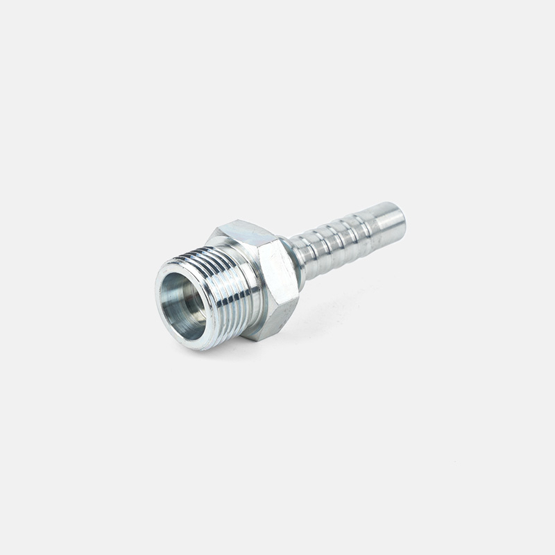

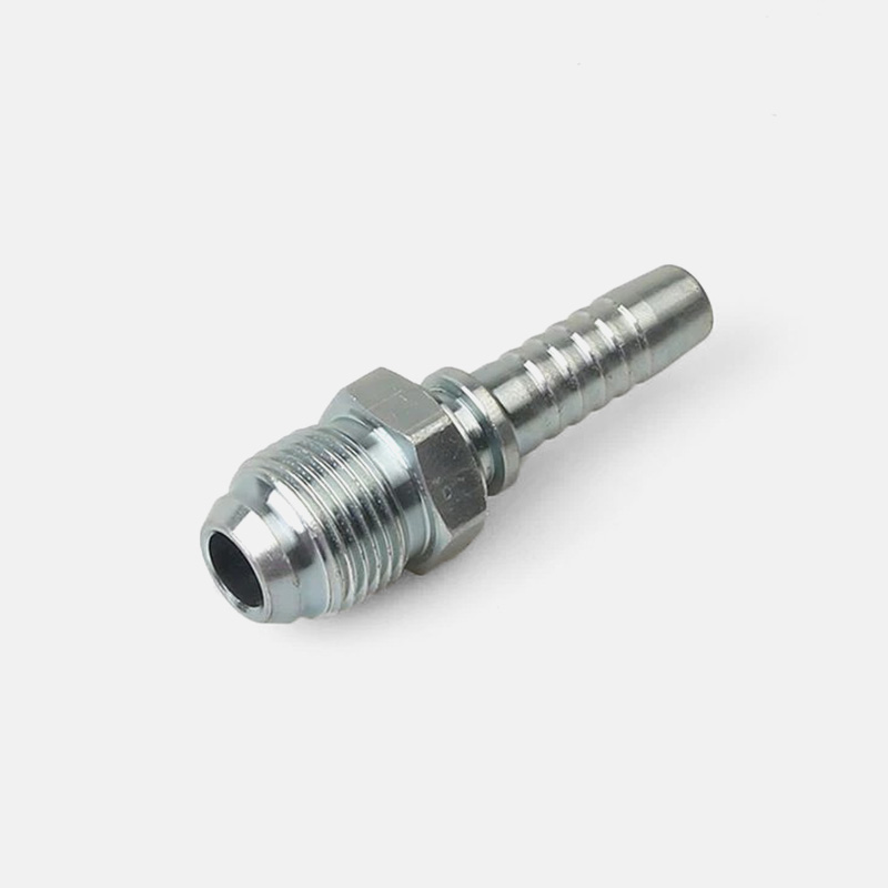
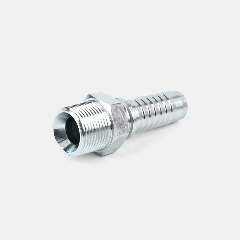


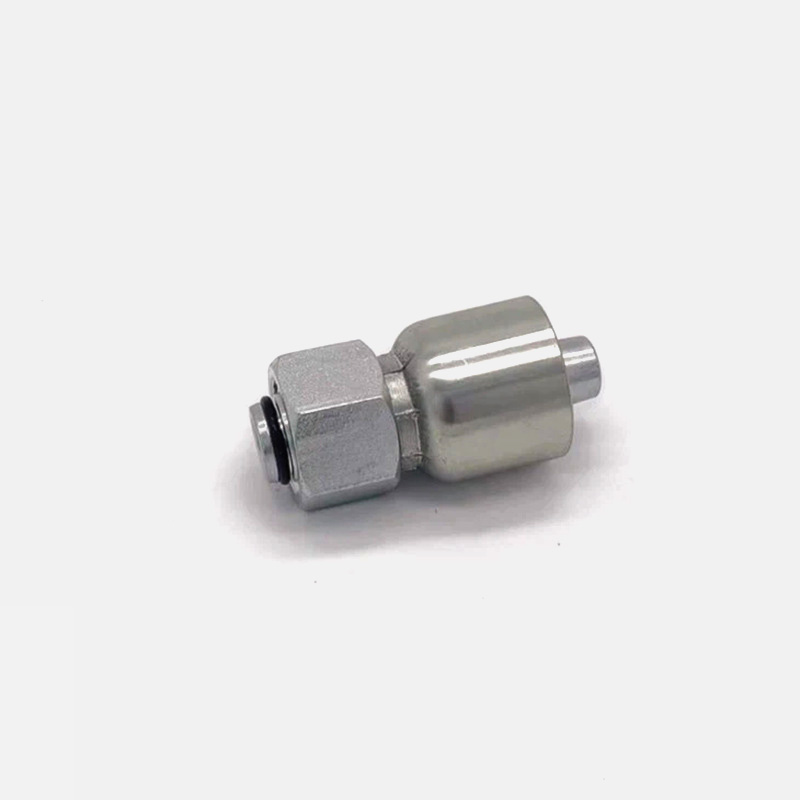
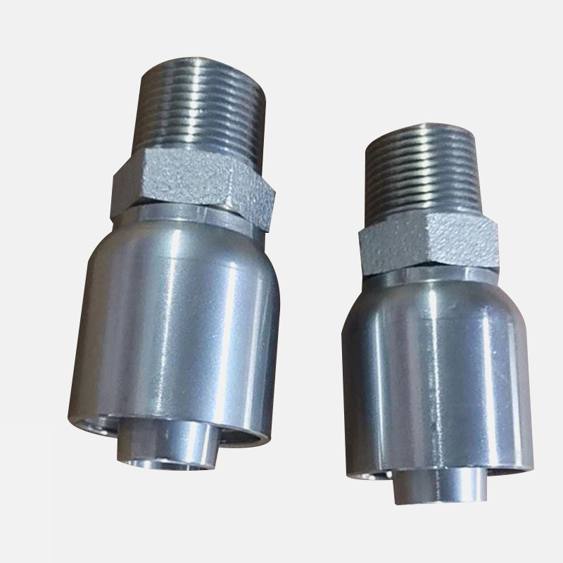

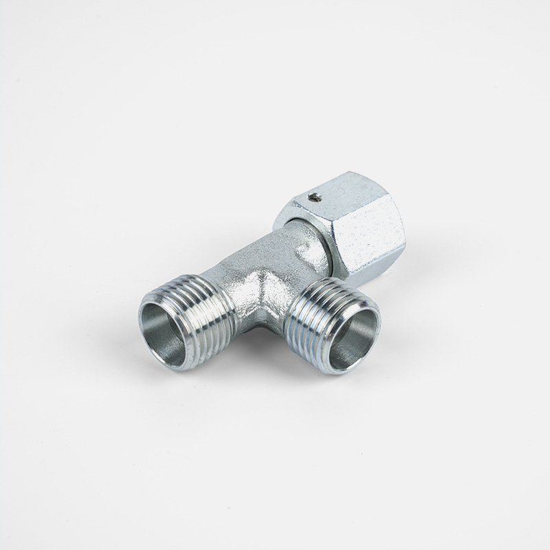
Accessoires hydrauliques sur mesure
Du concept à la production, nous pouvons créer les produits que vous souhaitez
Produits
- ·Raccords de tuyaux hydrauliques
- ·Adaptateurs hydrauliques
- ·Brides hydrauliques SAE
- ·Accessoires hydrauliques
- ·Robinet à bille hydraulique haute pression
- ·Raccord banjo
- ·Collier de serrage hydraulique
- ·Protection de ressort de tuyau hydraulique
- ·Viroles hydrauliques
- ·Raccords rapides hydrauliques
- ·Nouveau produit
Coordonnées
-

Tel: +86-159-6851-8588
-

E-mail: [email protected]
-

Add:Village de la gare de Zhu Jia, ville de Diankou, ville de Zhuji, province du Zhejiang, Chine
Lien rapide
Scanner le code
Droits d'auteur © Zhejiang Tianxiang Machine Fittings Co., Ltd.
